blogsdatasoftcomputers

Blogs.datasoftcomputers.in

Best Use Of Arduino With Relay

Learn how to control high voltage devices using a Arduino With Relay. Step-by-step wiring guide, code example, and practical applications explained for beginners.

Table of Contents

Introduction to Arduino and Relay

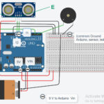
In many electronics projects, controlling high voltage devices like lights, fans, or appliances is necessary. Since Arduino operates at low voltage (5V), it cannot directly switch high voltage devices. This is where relay modules come into play.

A relay is an electrically operated switch that allows you to use a low-voltage signal from Arduino to control a high-voltage circuit safely. Whether you’re building a home automation system or controlling industrial equipment, using a relay with Arduino is a crucial skill.

Transistor Comes in between Arduino and Relay

A transistor is often placed between the Arduino and the relay to act as a switching amplifier—this allow Relays (especially mechanical ones) typically require 30mA to 60mA or more to energize the coil.

 Arduino digital pins can only supply ~20-30mA safely.

If you try to drive a relay directly, you could damage the Arduino, or it may not work at all. So, need of Transistor is reacquired to control the relay With Arduino more reliably and safely.

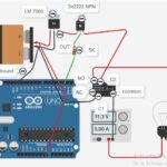
When the Arduino sends a HIGH signal to the base of the transistor. The transistor turns ON, allowing current to flow from collector to emitter, powering the relay coil. When the signal is LOW, the transistor turns OFF, cutting the current So This is the simple way to user Arduino with Relay.

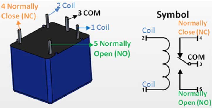
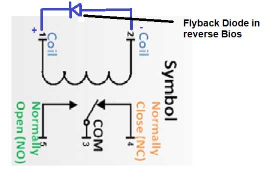
Short Overview of Relay:

Here I Am Using Simple Relay Not Relay Module. Relay Module Has Been Cover in Many Blogs.

In Simple relay when coil is charged then Normally open and Common points are connected, So AC circuit gets Complete To flow AC Current. 

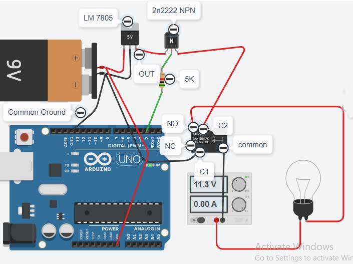
Transister Base gets Low Signal From Arduino (UNO, NANO etc.) and DC Current passes from Collector to Emitter. 

In Circuit We Can Join Relay in between Collector & Emitter Circuit.

Relay

Use flyback Diode in Relay

Relay Flyback Diode

Always use a Diode (IN4007) in Revere oder in between coils c1 & c2To reduce back EMF. It Will protect Aruino.

Relay Deals with High Ac Voltage, Always Make poper Security & precautions in AC Voltage, or work Under Guidance of Expert To Make projects to Use Relay in Circuit.

Component Required To Use Arduino With Relay

Components Required To Use Arduino With Relay

Wiring & Circuit Diagram

Circuit Diagram To Use Arduino With Relay

Program Video

Program Code

void setup()
{
pinMode(2, OUTPUT); //connected to base of transister
}

void loop()
{
digitalWrite(2, HIGH);// Transister Base gets High Current Passes from Collecter to Emitter. (Bulb Glows)
delay(1000); // Wait for 1000 millisecond(s)
digitalWrite(2, LOW);//Base gets Low Current Stops from Collector to Emitter.(Bulb Off).
delay(1000); // Wait for 1000 millisecond(s)
}

Key Points To Be Checked To Use Arduino With Relay In This Project:

  • Make Common Ground of Arduino and Battery.
  • Resistance Value connected to Base of Transistor May Vary According to Coil Activation current Requirement.
  •  Calculation for Base resistance is According to hfe value of Transistor.
  • Use fly back diode in Reverse polarity with Relay Coil.

Base Resister Calculation:

Suppose we have an NPN transistor with the following specifications:

  • IC (Collector Current) = 70 mA(required)
  • hFE (Current Gain) = 100
  • VBE (Base-Emitter Voltage) = 5v -0.7v(voltage drop in Transister)=4.3

Determine Base Current (IB):

  • IB = IC / hFE
  • IB = 70 mA / 100 = 0.7mA

Choose Desired Base-Emitter Voltage (VBE):

  • VBE = 4.3 V

Calculate Base Resistance (RB):

  • RB = VBE / IB
  • RB = 4.3V / .70 mA = 6 k

Use Of Flyback Diode In Relay:

A flyback diode in a relay circuit is used to protect switching components (such as transistors or microcontroller outputs) from voltage spikes generated when the relay coil is de-energized. When current through the inductive coil is suddenly interrupted, the collapsing magnetic field induces a high-voltage spike of opposite polarity (per Lenz’s Law and Faraday’s Law of Induction). This spike can exceed the voltage ratings of semiconductors and cause immediate or cumulative damage.

The flyback diode is connected in parallel with the relay coil, oriented so it does not conduct during normal operation. When the relay is switched off, the diode provides a low-resistance path for the inductor current, allowing it to recirculate and dissipate safely as the magnetic field collapses. This clamps the voltage across the coil to approximately the forward voltage drop of the diode (typically ~0.7V for silicon diodes), preventing high-voltage transients.

Summary of function:

Suppresses inductive voltage spikes

Protects switching devices from overvoltage

Ensures circuit longevity and reliability

Typical diode choice: 1N4007 or similar rectifier, rated for at least the relay coil current and reverse voltage.

You May Aslo Interested In:

Working of Arduino With Ultrasonic Sensor

Best Use Of Arduino With Ultrasonic Sensor

Best Use of Arduino With Ultrasonic Sensor (HC-SRO4) Learn how to use an Arduino with ...
Circuit Diagram To Use Arduino With Relay

Best Use Of Arduino With Relay

Best Use Of Arduino With Relay Learn how to control high voltage devices using a ...
LDR SENSOR WITH ARDUINO CONNECTION DIAGRAM 2

LDR Sensor With Arduino To Observe Light

LDR Sensor With ArduinoLDR Sensor With Arduino Nano To On/Off Light Project –Light Detection Made ...

Leave a Comment

Your email address will not be published. Required fields are marked *

Scroll to Top